
Boost the acoustic output of an electrical transducer with a si
-
Many different ideas have been proposed to increase the acoustic output of piezoelectric buzzers or ultrasonic transducers. Most of them involve fairly complex circuitry, adding to the overall cost of the solution. For example, boosting a low-voltage logic supply to a higher voltage or using an H-bridge topology is the most common solution.
In contrast, this design concept shows how to increase the acoustic output of a piezoelectric transducer while minimizing parts count and cost. Before looking at the new method, let's take a look at some of the most commonly used piezo acoustic designs and their drawbacks.

The simplest piezoelectric drive circuit consists of a transducer and a switching transistor (Figure 1). The voltage across the transducer cannot be greater than the supply voltage, which places an upper limit on the acoustic output. Resistor R2 is used to discharge the capacitance of the transducer. The RC time constant should be short relative to the period of the transducer's resonant frequency. Low resistance values reduce electrical efficiency while suppressing the mechanical (acoustic) resonance of the electrical transducer, which of course reduces acoustic efficiency.
Piezoelectric drive circuit
Although this piezoelectric drive circuit shown in Figure 1 is simple, it is very inefficient.
A common enhancement to this circuit is to replace R2 with an inductor, as shown in Figure 2. It is an improved piezo drive circuit.

The inductance value is usually chosen to electrically resonate with the capacitance of the transducer (buzzer) at the acoustic resonance of the transducer. This method can provide more sound output than the parallel resistor method, but there is still a lot of room for improvement. At best, the peak-to-peak voltage across the transducer can reach 40Vppk, with 20Vppk being more typical on a 5V supply.
This is because the transistor collector-base junction is forward-biased on the negative swing of the parallel resonant circuit formed by the inductor and transducer capacitance, thereby clamping the voltage swing and limiting the acoustic output.
Adding a diode decouples the CE junction (or, if using a FET, the body diode junction) from this negative swing, giving a larger voltage swing across the transducer and thus increasing the acoustic output (Figure 3). While the forward voltage of the diode does reduce the applied supply voltage, the increased resonant voltage more than makes up for this small loss.
Piezoelectric drive circuit diode
To achieve any further improvement, we need to consider that there are actually two resonances at play in this small system: the acoustic resonance of the transducer and the mechanical and cavity resonances where applicable.
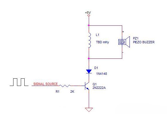
Figure 3 Using a diode can eliminate the negative swing of the circuit.
Electrical Resonance of Inductance and Transducer Capacitance
The electrical resonance frequency does not have to be the same as the acoustic resonance frequency. In fact, if it is about 2 times the acoustic resonance, the peak voltage across the transducer increases considerably.
This is demonstrated in Figure 4, where the waveforms were derived using the following circuit parameters:
Power = 5VDC
L1 = 3.2mHy
C (piezoelectric) = 2nF
Signal source frequency = PZ1, resonant frequency = 40KHz
Adjust signal source duty cycle to eliminate high current spikes at turn-on
Note that item 5 identifies a potential problem lurking in this new solution that must be addressed. If the signal source can turn on the transistor after the transducer voltage becomes positive, there will be a large narrow current spike, which reduces electrical efficiency and may degrade the transistor's performance over time. Increasing the duty cycle to cause the transistor to conduct while the resonant voltage is slightly negative removes this spike.

With everything sorted out, let's see how our circuit behaves in real life using a handy four-trace smart oscilloscope:
Yellow = drive voltage, ~48% duty cycle, 5Vppk. at 40KHz
Purple = electrical resonant voltage across the transducer, 92Vppk. at 80KHz
Green = Transistor emitter current, about 80mA peak at 40KHz
Blue = acoustic output of transducer, measured with MEMS microphone
Piezoelectric drive circuit waveform
Figure 4 This is how the circuit behaves in real life.
The high peak voltage across the transducer is achieved by using a smaller inductor than the one that resonates at 40KHz, allowing the current to rise about twice as fast, and in this example, provide twice the current to "charge"? The magnetic field of the inductor.
Peak voltage is similar to pushing on a swing, the higher the available peak voltage, the stronger the pushing force provided. In this system, this translates into the greater displacement of the transducer face, resulting in greater acoustic output.
This design concept is not an exhaustive treatise on resonant circuits. Instead, it demonstrates a procedure by which any resonant piezoelectric transducer or buzzer can be driven to a loud output using a very simple, low-cost circuit.
Conclusion
Determining the Acoustic Resonant Frequency of the Transducer
Create a train of drive pulses at the same frequency, starting with a 50% duty cycle
Adjust duty cycle as needed to eliminate current spikes at turn-on
Determining the Capacitance Value of the Transducer
Choose an inductance value that will resonate electrically at about twice the acoustic resonance.
It may be difficult to replicate the acoustics/circuitry presented here in a simulation because the transducer consists of two or more potentially resonant elements. These include the mechanical resonance of the transducer element, the acoustic resonance of the transducer housing (see Helmholtz resonance), and of course the electrical resonance of the transducer capacitance with the external inductance.
Radiated acoustic loading from the transducer port or diaphragm adds another difficulty to the simulation. A simple electrical simulation of this circuit produced 240Vppk across the transducer, more than double that produced in the actual circuit. Acoustic loading likely represents most of the penalty for reducing the peak transducer voltage in this system compared to simulated results.
By using this simple procedure, it is easy to maximize sensor output with minimal time and effort.